PD4-A Series
AC power cable will be included in the standard model.
AC power cable will not be included in the model with "-NC" at the end.
The product with the model name with "-NC" at the end conforms to the KC standards.
For customers in Korea and Europe, please select model name with "-NC" at the end.
Features
Features
- Continuous lighting, ON/OFF mode, or strobe mode
- Lighting output capacity: 30W / 120W available
- Channel options: 30W with 2 channels/4 channels, 120W with 8 channels
- Ethernet / parallel external control
- Trigger input signals and parallel input signals support both NPN and PNP connection
- 1,024 steps of precise intensity settings*
- All types feature natural air cooling, improving installability
- Can be switched to PWM frequency 500 kHz mode*
- Trigger input signal and parallel input signal 5 V input is possible
*256 light intensity setting levels in PWM frequency 500 kHz mode for the PD4-A Series
Various Lighting Control Functions
- Turn lights on in desired pattern with sequence control function
- Supports PLC link function for easy integration with PLCs
- Trigger output function simplifies the synchronization of the camera and lighting
- With Recipes setting, save lighting settings in a maximum of 8 recipes
- Real-time information monitoring from applications, such as operating status and operation logs
Lineup of PD4/PD4-A Series
We have expanded the PD4 lineup to include the PD4-A Series, which features new lighting control functions.


External control is indicated by the E and P at the end. E: Ethernet P: Parallel
AC power cable will be included in the standard model. AC power cable will not be included in the model with "-NC" at the end.
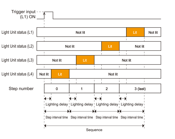
Sequence
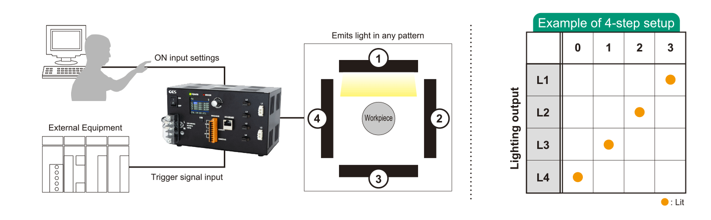
Turn lights on in desired pattern with sequence control function
Program up to 16 steps of ON input for a pattern of light emission.
For example, when using 4-quadrant bar lights or segmented lights to illuminate from multiple directions,
the emission patterns for each channel can be stored and switched ON / OFF by trigger input.
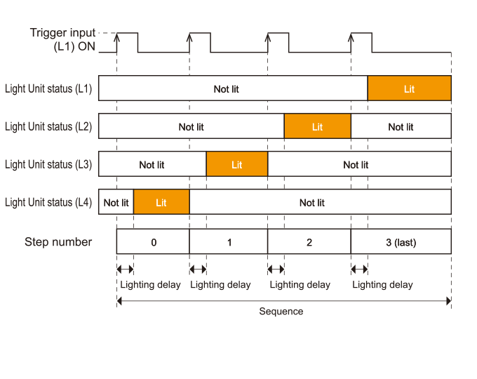
Difference in lighting operation depending on trigger operation mode setting values
Program a maximum of 16 steps of ON input.
Sequence operation can be performed with multiple steps per trigger or 1 step per trigger.
■Limited function for PD4-A
- In addition to lighting pattern, light intensity and lighting time can also be set in levels
- Added function enabling change of lighting pattern implementation order and multiple implementations (up to 32 times)
- Added mode enabling change of sequence numbers in trigger operation mode via trigger input
When the Set Value of the Trigger Operation : Mode Is 1-Trigger 1-Step Sequence Operation
When the Set Value of the Trigger Operation : Mode Is 1-Trigger N-Steps Sequence Operation
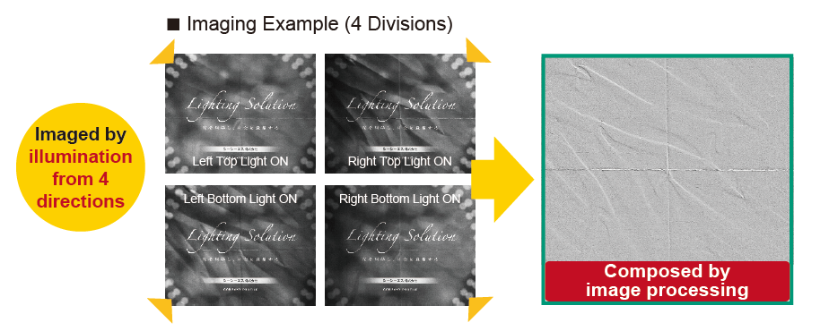
Sequence Control Application Examples: Imaging using photometric stereo method
The workpiece is illuminated and imaged in each direction.
It is possible to generate images that highlight only the unevenness or extract only the pattern by using the differences of each captured image.
Character inspection of patterned tiles
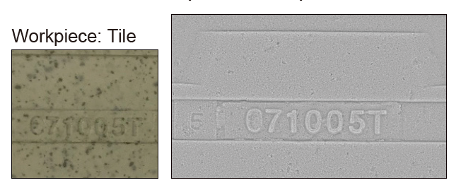
By removing patterns and extracting unevenness,
it is possible to acquire images in which characters can be easily recognized.
Surface imaging on rubber products
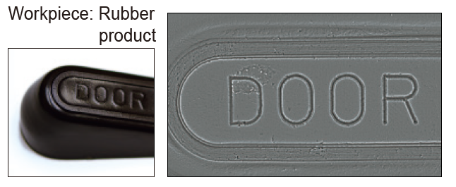
By enhancing the unevenness of the rubber product,
it is possible to acquire images in which characters can be easily recognized.
Heat seal inspection
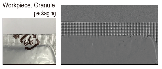
Removes the pattern and halation and obtains information on the unevenness of the heat seal.
For details, see "Sequence Control" on page 10 of the operation manual.
Trigger Output Mode
Trigger signal can be output from the control unit
This function can be used as a trigger signal for the camera.
By simply setting the parameters of the PD4-A, it is possible to synchronize the lighting and camera.
■ Trigger Output Application Example
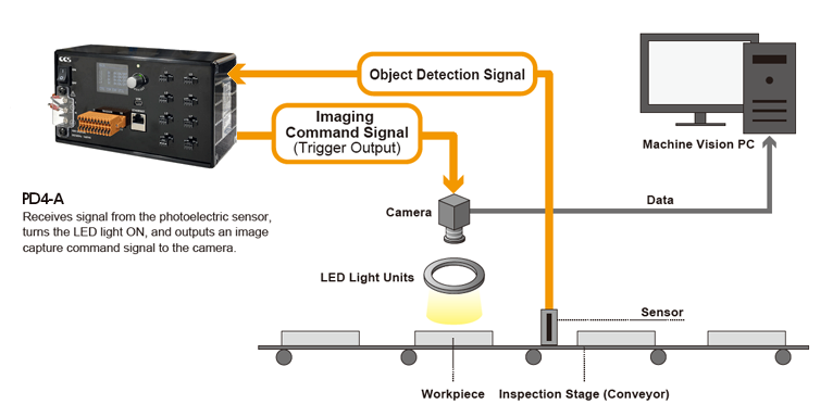
■ Trigger Output Signal Connection Example
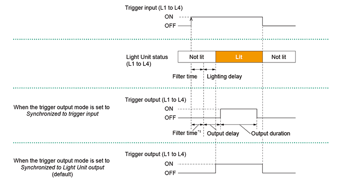
*1 Setting time of the filter for noise suppression.
Recipes
Save lighting settings in a maximum of 8 recipes
Parameter settings such as intensity values for each channel and other inspection-specific parameter settings can be registered in advance, allowing for easy setting changes simply by recalling recipes.

Application
Application
It is possible to intuitively set various lighting parameters.
The PD4-A Series main unit is equipped with two modes: "Simple Mode", which focuses on basic functions such as intensity value and ON/OFF settings, and "Normal Mode".
The application with the same mode as the main unit will automatically start.
Simple mode
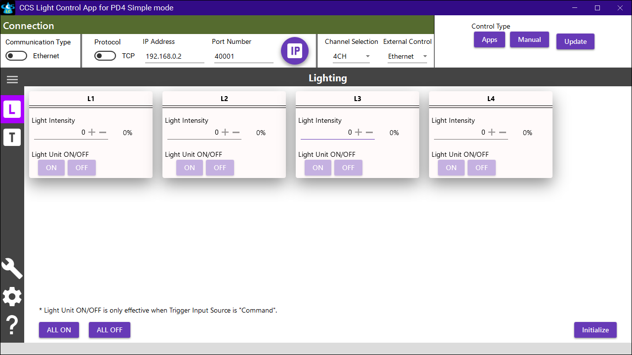
Basic lighting settings such as intensity value and lighting time, as well as trigger input assignments to lighting outputs, are possible.
Normal mode
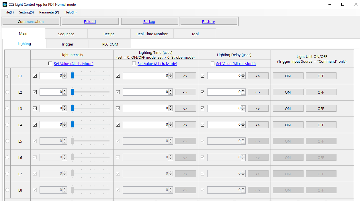
In addition to the functions of the Simple Mode, all functions of the PD4-A Series can be configured, including sequence control, real-time monitoring functions, etc.
- This application is dedicated to the PD4-A Series. (Cannot be used with the PD4 Series.)
- Please check "System Requirements for Product Applications" for the system requirements of this program.
- The application can be downloaded from "Product Lineup"
Communication function
PLCCOM Communication
Supports PLC link function for easy integration with PLCs
PLCCOM communication allows the product to be controlled by reading and writing memory areas on the PLC via Ethernet. Easy to install because there is no need to create a program specifically for the control unit.
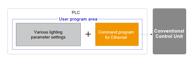
Without PLCCOM Communication [For Conventional Control Units]
A program is needed to communicate with the control unit separately from the various lighting parameter settings.
With PLCCOM Communication [For PD4/PD4-A]
Can be connected via the PLC function, so there is no need to build a communication program.
![With PLCCOM Communication [For PD4]](/shared/images/products/uploads/PD4-A/PD4_communication_02_e.png)
PLCCOM Communication Specifications
| For PLCs supporting MC protocol | For PLCs supporting FINS commands |
|---|---|
| • Device : Data register
• Protocol : MC protocol for MELSEC-Q series • Frame : 3E frame • Transmission code : Binary • Transport : TCP or UDP |
• I/O Memory : DM Area
• Protocol : FINS Commands • Transmission code : Binary • Transport : TCP or UDP • FINS node address : For the TCP setting, specify the address that is automatically assigned by the PLC. For the UDP setting, specify the 4th octet of the IP address of the Control Unit. (Eg. When the IP address is 192.168.0.123, specify 123.) |
For details, see " 7.3 PLCCOM Communication Overview" of the operation manual.
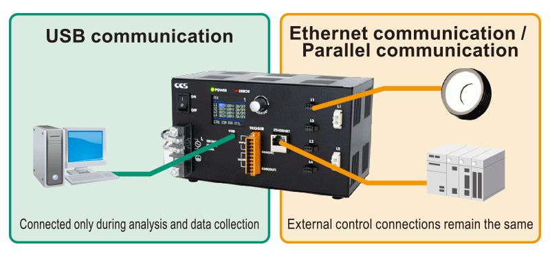
USB Communication
Equipped with a USB connector to enable data communication with a PC while connected to external control devices
Various settings and operations can be verified via USB communication.
Use a USB cable with a ferrite core.
USB Connection Image
Options
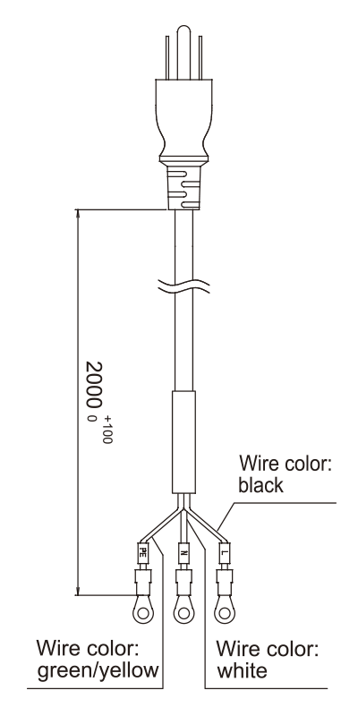
Cable
Prong AC Power Cable with Ground Terminal (100-120VAC, 2m)
ACC-JIS-125-7-M4-2
AC power cable will be included in the standard model.
AC power cable will not be included in the model with
"-NC" at the end.
E.g. PD4-3024A-4-P (included)
PD4-3024A-4-P-NC (not included)
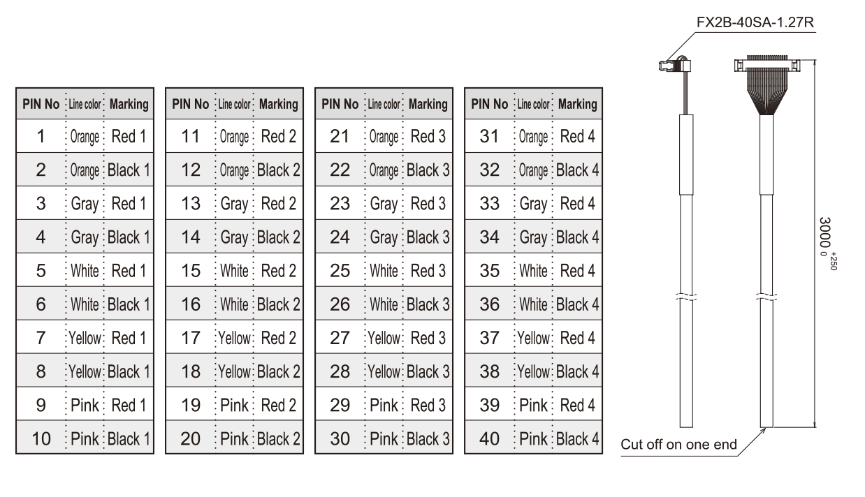
Parallel Communication Cable (Sold Separately)
EXCB2-FX40-3
Parallel communication cable
Spot Lighting Connection Adapter for PD4-A Series (RB-HLV Series)
Dedicated adapter for connecting HLV3 Series to PD4-A Series*
・Enables use of HLV Series with brightness equivalent to
when using the PJ2 Series spot lighting control unit
・Enables use of HLV Series with response speed equivalent
to 24 V lighting
・Eliminates the need for a dedicated spot lighting control unit,
reducing setup time and saving space
For more details, please refer to the 'RB-HLV Series' page.
Software Tools
Application Note
| Title | Functional Classification | Download | Last Update |
|---|---|---|---|
| Sequence control that changes light intensity and lighting time in each step | Sequence | 2025/3/7 | |
| Sequence control that operates two or more sequences simultaneously | Sequence | 2025/3/7 | |
| Sequence control that executes each step in an arbitrary order | Sequence | 2025/3/7 | |
| Individual lighting confirmation in sequence control | Sequence | 2025/3/7 | |
| Multiple image inspections achievable with a single trigger input | Sequence, Trigger output |
2025/3/7 | |
| Operation mode in trigger output | Trigger output | 2025/3/7 | |
| Simple method for synchronizing with a camera using the trigger output function | Trigger output | 2025/3/7 | |
| How to communicate with PLCs using the PLCCOM function (Mitsubishi Electric PLC version) |
PLCCOM | 2025/3/7 | |
| PLC communication using the easy setup mode of the PLCCOM function | PLCCOM | 2025/3/7 | |
| PLC communication using the easy setup mode of the PLCCOM function | PLCCOM | 2025/3/7 | |
| How to communicate with PLCs using the PLCCOM function (Panasonic PLC version) |
PLCCOM | 2025/3/7 | |
| How to communicate with PLCs using the PLCCOM function (Keyence PLC version) |
PLCCOM | 2025/3/7 | |
| Functionality of the 'Simple mode' in the firmware switching function | Firmware switching | 2025/3/7 | |
| Method for confirming synchronization with a camera using the internal trigger function | Internal oscillation function | 2025/3/7 |
Products
-
Machine Vision Applications
Ring
Low-angle Ring
Waterproof Ring
Bar (Area)
Low-angle Square
Flat
Flat Dome
Line Pattern
Dome
Coaxial
Cylinder
High Power Strobe
UV Lights [Ultraviolet Lighting] / Violet Light
IR Lights [Infrared Lighting] (under 1000nm)
IR Lights [Infrared Lighting] (over 1000nm)
Spot
Fiber Heads
Light Source Unit
Line (Convergent Lighting)
Line (Diffused Lighting)
Line (Oblique Angled Lighting)
Reference Light Source
Lights for Fringe Interference Inspection
Custom Order Product
Intensity Control Units [Light Units with Intensity Control Unit ]
Effilux Products
Basler Camera Light Series
- BCL Series (Bar Light)
- BCR Series (Ring Light)
- BCBL Series (Flat Light)
- BCF Series (Flood Light)
- BCL Series (Bar Light) Diffusion Plates
- BCR Series (Ring Light) Diffusion Plates
- BCF Series (Flood Light) Transparent Plate
- BCL Series (Bar Light) Light Polarizing Plates
- BCR Series (Ring Light) Polarizing Plates
- BCF Series (Flood Light) Polarizing Plates
- BCR Series (Ring Light) Light Adapter
- BCL Series (Bar Light) Light Bracket
- Basler Camera Light dedicated cable
-
Control Units
Digital Control Units
Strobe Unit
High Power Strobe Control Unit
PoE Enabled Controller
Controller with EtherNet/IP Interface
LED Light Controller
Control Units [for the HLV Series]
High-capacity Constant-current Control Units
High-capacity Analog Control Unit
Control Units [for CCS AItec]
-
Cables
Straight Cables
2-way Cables
4-way Cables
Robot Cables
2-way Robot Cables
4-way Robot Cables
Straight Cables [EL connector type]
2-way Cables [EL connector type]
Extension Cable [for PF Series]
Straight Cables for metal connector (7 pins)
Straight Cables for metal connector (37 pins)
Straight Cables for M12 connector
External Control Cables
Relay Connector
AC Power Cable
-
Options
Filters
Diffusion Plates
- Diffusion Plates [for Ring Lights]
- Diffusion Plates [for LDR-PF Series]
- Diffusion Plates [for LDR-PF-LA Series]
- Diffusion Plates [for Low-angle Ring Lights]
- Diffusion Plates [for Bar Lights]
- Diffusion Plates [for LDL-PF Series]
- Diffusion Plates [for HLDL3 Series]
- Diffusion Plates [for LB Series]
- Diffusion Plates [for Coaxial Lights]
- DF Series
- DF80 Series
Polarizing Plates
- Polarizing Plates [for Ring Lights]
- Polarizing Plates [for LDR-PF Series]
- Polarizing Plates [for Bar Lights]
- Polarizing Plates [for LDL-PF Series]
- Polarizing Plates [for HLDL3 Series]
- Polarizing Plates [for LB Series]
- Polarizing Plates [for Coaxial Lights]
- Polarizing Plates [for IR Series Infrared Lights (over 1000-nm type)]
- PL Series (FASTUS)
Light Control Films
Protective Plates
Adapter [for the CSR Series]
Lens Attachment Rings
Fixtures
Fixtures
Converter
Coaxial Units
Reflection Plate
Condenser lens
-
Lenses
Telecentric Lenses
Macro Lenses
-
Software Tools
Program for controllers
Version Upgrade for controllers
Application note for controllers
-
Agri-Bio Lighting
LED Light Units for Plant Research
ISL-150X150 Series Unit
ISL-150X150 series cables
-
Human Vision Inspection and Microscope Applications
LED Light Units for Microscopes
 Request Free Trial
 Request Quotation
 Inquiry Form
 Locations