Theory of Light and Color

10. The Relationship Between Illuminance and Luminance on Reflecting Surfaces
This chapter reviews the relationship between illuminance and luminance on a reflecting surface. This relationship concerns any instance of observing an illuminated object, whether with human vision or machine vision.
The same relationship exists between irradiance and radiance, as well as sensor-metric illuminance and sensor-metric luminance.
The Reflecting Surface as a Secondary Light Source
As discussed in Chapter 9, a reflecting surface is in theory a secondary light source.
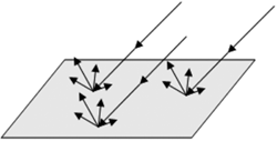
Illuminance is an index of how much luminous flux is incident on a surface (per unit area). Luminance is how much luminous flux is reflected from that surface (per unit area) in a given direction.
So the illuminance that hits a reflecting surface "turns into" luminance. Unless reflectance is zero, we can call the surface a secondary light source.
The Relationship Between Illuminance and Luminous Exitance on Reflecting Surfaces
The following formulas express
- ● Illuminance (E): the luminous flux (φIN [lm]) per unit area (A [m2])
- ● Luminous exitance (M): the luminous flux (φOUT [lm]) emitted from a unit area (A [m2])
- ● Reflectance (ρ): the ratio of reflected luminous flux (φOUT) to incident luminous flux (φIN), where in general ρ < 1

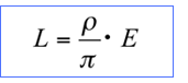
You can then see the relationship between illuminance (E) and luminous exitance (M). ≪1≫
M = ρ・E
Reflection on the Object Surface
Luminous exitance (M) is the sum of all luminous flux traveling toward a half-space (2π space) from the light source or the reflecting surface (secondary light source). It is not a direct measure of how bright the reflecting surface appears. For example, a glossy surface appears brighter from the angle of regular reflection than from other angles. You need to measure using luminance (L). The figure below illustrates several examples of reflected light distribution on different surfaces. ≪2≫
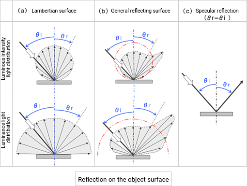
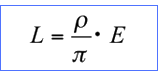
The Relationship Between Illuminance (E) and Luminance (L) on a Lambertian Surface
When a light source illuminates a Lambertian surface, there is an important relationship between the illuminance (E) [lx] and luminance (L) [cd / m2] of the surface. ≪3≫
When the reflectance (ρ) is fixed ≪1≫, the luminance (L) is proportionate to the illuminance (E). The higher the illuminance (E), the greater the luminance (L) of the surface.
And if the illuminance (E) of the light source is fixed, the luminance (L) increases the more reflectance (ρ) there is.
As described in Chapter 9, the relationship between illuminance and luminance is simple for a Lambertian surface. Luminance is constant from any angle of illumination and angle of view.
As such, a Lambertian surface is the simplest form of reflection. Therefore, it is widely used as the standard for various photometric and colorimetric measurements and the calibration of measuring instruments. ≪4≫
The Relationship Between Illuminance (E) and Luminance (L) for Non-Lambertian Surfaces
The real relationship between illuminance (E) and luminance (L) of a surface is more complex. It varies with the material of the surface and the direction.
A typical surface is not Lambertian like the one in Fig. (a). In general, the luminous intensity increases in the specular direction and decreases as it moves away, as shown in Fig. (b). As the surface becomes glossier, the luminous intensity in the specular direction increases until it is completely specular like Fig. (c).
The Standard for Diffuse Reflection Distribution
A perfect reflecting diffuser is an ideal diffuse reflecting surface with 100% reflectance. It is a standard for evaluating the distribution of diffuse reflection.
The ratio of the luminance of a surface L(θr) to the luminance of a perfect diffuser LPD is the luminance factor, represented by β. (PD = Perfect Diffuser)
LPD is constant regardless of the angle of reflection (θr), while L(θr) changes depending on (θr).
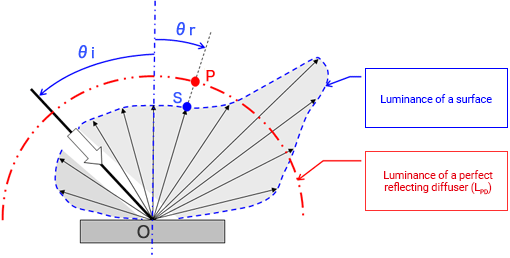
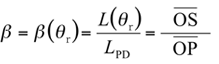
Luminance L(θr) of a given area at angle of reflection θr is β (θr) times the luminance of the perfect reflecting diffuser (LPD). For a glossy surface, the luminance will be much higher at the angle of regular reflection compared to a perfect reflecting diffuser (β >> 1).
Information Extraction in Machine Vision
The above uses a fixed angle of incidence (θi) to simplify our explanation. If the angle of incidence (θi) changes, the angle of regular reflection changes as well. The luminance factor β is thus a function of both the angle of incidence (θi) and the angle of view (angle of reflection θr).
β = β ( θi, θr )
In machine vision, you adjust both angles to get the greatest difference in the light distribution reflected off the target information versus the rest of the surface. By doing so, you get a high signal-to-noise ratio (S/N). This is one of the most important techniques in machine vision.
Comment
≪1≫ Reflectance (ρ)
Reflectance is the ratio of the total reflected luminous flux to the total incident luminous flux. It covers all reflected luminous flux from every direction, both regular and diffused reflection.
It is different from solid angle reflectance, which refers to taking an image of a certain area from every direction. Solid angle reflectance is the ratio of the reflected luminous flux on a sample surface to that on the perfect diffuse reflector. It encompasses only the reflected luminous flux within the solid angle determined by the lens aperture and the camera position relative to the surface. (See JIS Z 8113: 1998 [04062] [04072])
≪2≫ Illustrating light distribution characteristics with luminous intensity and luminance
Light distribution characteristics show the amount of luminous flux that is emitted from a light-emitting point in a given direction. That is why light distribution characteristics are usually expressed as luminous intensity.
Light distribution characteristics can also be expressed as luminance. But the luminance of an emitting surface (light source and reflecting surface) changes with the angle of view. Measuring the same surface with luminous intensity and with luminance can have completely different results.
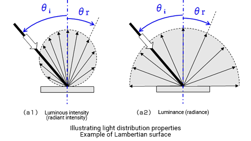
Luminance is the luminous intensity per apparent unit area. If a particular surface area is A, its apparent area viewed from an oblique direction θ is A・cosθ. The luminance equals luminous intensity divided by A・cosθ.
Fig. (a1) shows the light distribution characteristics of a Lambertian surface, expressed as I (θ)=I0・cosθ.
I0 is the luminous intensity in the direction of the surface normal, so the luminance L(θ) in direction (θ) is
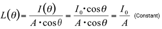
This means that luminance is the same from any angle (brightness appears the same). Fig. (a2) illustrates the luminance light distribution characteristics.
≪3≫ Relationship between illuminance (E) and luminance (L) on a Lambertian surface
Consider a case where the surface is illuminated by illuminance (E). If the incident luminous flux to a particular area (A [m2]) is φIN [lm], illuminance (E) [lx] can be written as

The luminous flux φIN [lm] is partly absorbed and partly reflected. The total luminous flux reflected off the area (A [m2]) is φOUT [lm] and can be expressed as

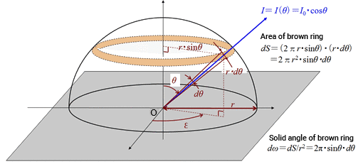
An ideal Lambertian surface shows spherical light distribution characteristics at any angle of illumination, as shown in Fig. (a). It is rotationally symmetric around the normal. In other words, the luminous intensity distribution characteristics of a Lambertian surface are constant in the circumferential direction (angle ε direction). It changes only with angle θ from the normal, written as
I(θ) = I0 cos θ
The figure shows a hypothetical sphere with radius (r) centered on point (O) of the surface. The brown ring is the area cut at a small angle in the θ direction dθ from point (O). The density of luminous flux passing through the brown ring is uniform for a Lambertian surface.
If the area of the ring is dS,
dS = ( 2π・r・sinθ )・( r・dθ ) = 2π r 2・sinθ・dθ
The solid angle (dω) of the ring is
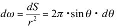
Thus, the total reflected luminous flux φOUT [lm] of the Lambertian surface is
In other words, the luminous intensity in the normal direction (I0) for a Lambertian surface is the total reflected luminous flux φOUT divided by π.
If the luminous flux reflected off the Lambertian surface is viewed from angle(θ), the luminance L(θ) is
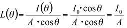
The cosθ of the luminous intensity I(θ) and that of the apparent area cancel each other out. This means the luminance L(θ) is constant regardless of the angle (θ).
From the above, we get the following
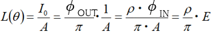
Thus, we can see the relationship between the luminance (L) of a Lambertian surface and the illuminance (E) that hits the surface, which is independent of the angle of illumination and the angle of view.
≪4≫ White reflectance standard
A white reflectance standard is a near Lambertian surface, with a constant spectral reflectance of 90% or more over its entire wavelength range. It is generally used for calibrating a luminance meter or colorimeter.
Radiant Quantities and Luminous Quantities (Part 4)
Luminous intensity / Radiant intensity and Luminance / Radiance